This article addresses the impact of operational factors including current density, voltage fluctuations, transient and variable loads, water purity, and internal electrolyser conditions on the durability and stability of alternative electrolysers deployed in large scale green hydrogen. I will consider existing commercialized electrolyser technology, namely Alkali Water Electrolysers (AWE), and Proton Exchange Membrane (PEM) types. AWEs are characterized by high stack lifetimes of up to 80,000 hours, while PEM electrolysers have lifetimes in the 30-60,000 hour range.
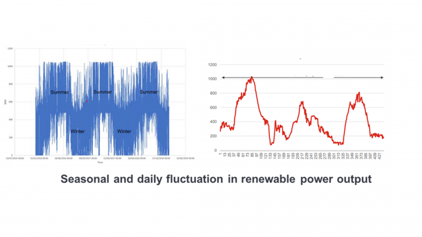
However, there is uncertainty around the durability and longevity of electrolysers at scale, particularly given that these will be subject to frequent intraday and seasonal load changes associated with linkage to variable renewable energy (VRE) sources, as shown in the figure below.

There is therefore a risk that high maintenance and repair costs caused by shutdowns to carry out corrective maintenance will directly impact the revenue stream of project owners, leading to higher Business Interruption (BI) exposure and potentially also limiting the developer’s ability to repay debt.
We will look in turn at the expected failure modes of both PEM and AWE electrolyser stacks, and then consider how design features, online measurement of operational parameters, and a combination of predictive and preventative maintenance can reduce the risk of failure and extend cell/stack life.
PEM Electrolysers – Key Failure Mechanisms
Some of the potential key failure modes for PEM cells are:
- Precipitates from water (e.g. Ca2+ and other metal cations) which can reduce active catalyst and membrane area by blocking active sites for the hydrogen evolution reaction;
- Iridium dissolution from the anode catalyst site due to the formation of soluble iridium complexes caused by high voltage overpotentials across the membrane;
- Membrane fluoride ion loss – operating at higher current density or chemical attack by radicals results in breakdown of the ionomer which reduces lifetime of cell; and;
- Hydrogen loss at the cathode leading to oxidation and degradation of carbon supported catalysts layers and Gas Diffusion Layer, including through the formation of hydrogen peroxide.
Predicting PEM Failures
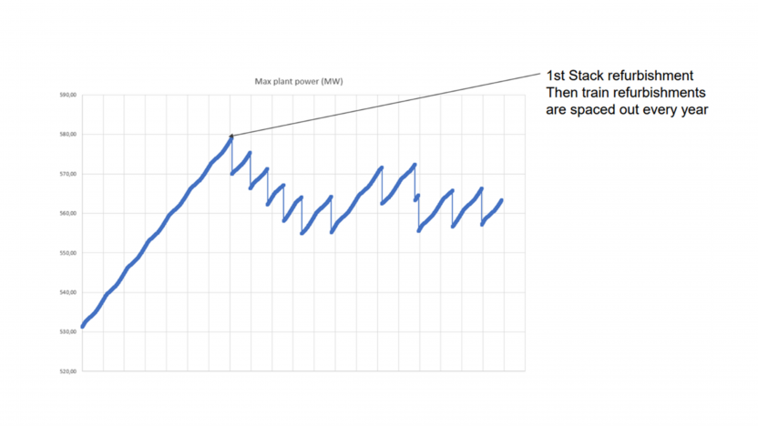
All of these failure mechanisms can be measured either by deionised water analysis, conductivity changes or increase in cell voltage via increased resistance and therefore can be used to actively predict cell failure. The figure below demonstrates how the power demand for a green hydrogen plant increases as cells and stacks begin to degrade. Refurbishing and replacing membranes and stacks leads to some recovery of performance. Electrolyser OEMs recommend complete stack replacements (end of life) when the voltage / power required is 20% higher than at initial operation (start of life) based on a trade-off with higher electricity costs.

Other PEM Damage Mechanisms
PEM electrolysers have several other likely failure mechanisms, including mechanical damage to the membrane electrode assembly (MEA) which could be caused by non-uniform clamping stresses, swelling or shrinking of the membrane, pinholes introduced during MEA manufacture, non-uniform water uptake or water starvation. Large gas bubbles caused by high current densities can lead to water starvation effects by limiting mass transfer.
Due to the corrosive (perfluorosolphonic acid - PFSA) electrolyte environment in PEM electrolysers, there are a number of corrosion damage mechanisms that need to be addressed. Operation outside (above) 50–80℃ in temperature will accelerate corrosion, which may result in short circuiting of individual cells. The titanium bipolar plate will be susceptible to oxidation and corrosion by fluoride ions, whilst stainless-steel materials will be corroded by acid. All stainless-steel components, e.g. end plates, must therefore receive passivation treatment following machining. Similar corrosion mechanisms will be at work in the current collector. Hydrogen absorption and embrittlement of these components also needs to be designed for.
The frequent load changes that an electrolyser experiences, due to fluctuating renewable energy profiles, has been shown to accelerate corrosion of stack components, leading to membrane thinning and impacting structural integrity of the MEA. Thicker membranes are required to resist this structural degradation, but these in turn have higher ohmic resistance, lowering cell efficiency.
PEM Electrolysers - Innovations for Extended Lifetime
This challenge is being addressed by a number of innovations in membrane design and stack operation, including:
- Material science developments such as the addition of graphene to the membrane structure, improving durability, thermal stability and tensile strength, resulting in extended operating hours between replacements. Some OEMs are also developing super-hydrophilic electrodes to increase wettability between the catalyst and electrolyte;
- Membrane treatments, such as acid doping, which allow them to be more resistant to the highly acidic conditions that PEM electrolyser membranes operate under, or eliminating fluor-membranes, again leading to extended lifetimes;
- Bespoke feed water treatment processes. Poor water quality is one of the main reasons for failures in PEM electrolysers. OEM recommendations regarding water treatment should be followed and quality specifications set out in ASTM D1193 for Type III (deionised) quality water.
- Supervisory control systems complete with intra-day power forecasting which anticipates load changes and allows the supervision system to:
- Avoid starting/shutting down unnecessary units during power fluctuations;
- Anticipate the number of running units to limit stack degradation and cyclic loading;
- Shut down some units to allow Preventative Maintenance (PM) and staggered stack refurbishment.
- Supplement variable renewable energy sources with power from the grid or from battery energy storage (BESS). This solution is being adopted by a number of Gigascale green hydrogen projects. The Neom project in Saudi Arabia includes a 40 MW/ 40 MWh BESS to allow some trains to run at minimum load to improve system resilience to intermittent electrical supply.
AWE Electolysers – Predicting Failure and Extending Life
The green hydrogen industry can benefit here from the field of chlor-alkali production for which cathodes have been developed that are resistant to shutdowns. In addition, technologies have been developed for monitoring cell voltage across individual cells in chlor-alkali technologies by companies such as the R2 Intelligent Technologies EMOS system. This technology is now being applied by some AWE OEMs to identify individual cells/membranes/separators that are underperforming. In the case of large-scale hydrogen production, each AWE can contain hundreds of cells. This is a significant risk mitigation as while the electrolyser voltage looks normal, individual cell voltages may already be abnormally high.
Continuous individual cell voltage monitoring allows fast replacement of individual underperforming cells, rather than replacement of an entire stack. This minimises downtime associated with replacement, by identifying individual ‘bad actor’ cells rather than needing to replace the entire stack. However, the technology currently can only be applied for cell replacement in AWEs which have been manufactured using hydraulic filter press methods.
Conclusion
There is uncertainty about the longevity of large-scale electrolysers for green hydrogen production. In order to assess the expected lifetime of electrolysers, insurers should consider requesting OEMs to perform Accelerated Degradation Testing (ADT) using degradation accelerating parameters including high current density and high operating temperature. This can be used to simulate actual conditions and degradation mechanisms over a short timescale, and to thereby monitor parameters defining ageing and integrate into Equivalent Operating Hours (EOH) assessments.
Potentially high OPEX (power import), maintenance and repair costs can be mitigated by OEMs offering long term performance warranties on critical components, including replacement of defective components. Given the long lead times for replacement of some electrolyser components, Long Term Service agreements (LTSAs) with OEMs should be considered, such as larger spares inventories, stack refurbishment services, and on-line condition monitoring.
Other critical factors impacting electrolyser reliability and durability covered in this article include:
Material Quality: Utilising high-quality, durable electrodes and stack assemblies is essential for the long-term efficiency and reliability of an electrolyser, as these materials need to withstand harsh chemical and electrical environments.
Operating Conditions: Extreme variations in temperature, pressure, or flow rate can accelerate wear and tear, emphasizing the need for consistent operating conditions to extend the electrolyser's lifespan and maintain its performance. AWEs operate optimally with steady state power profiles, whereas PEM electrolysers can handle variable power profiles expected from renewables. Operating within operational windows is critical to electrolyser durability. Commissioning, Operations and Maintenance teams core competencies include monitoring operating limits (T, P, flow, concentrations, voltage), checking for transient operations during commissioning, implementing systems logic alarm and trip thresholds and optimising any changes in operational modes (on/off vs turndown).
Contaminant Management: Impurities within the feedstock, such as minerals or gases, can lead to corrosion and fouling of crucial components. Proper water purification processes and filtration and maintenance of these systems are necessary to prevent buildup of these contaminants, ensuring the system operates smoothly over time. PEM is particularly sensitive to water impurities.
Electrolyte Purity: The purity and consistency of the electrolyte solution are fundamental. Maintaining a clean and uncontaminated electrolyte is vital to prevent degradation of electrodes and membranes, thus preserving the efficiency of the electrolysis process. Poor electrolyte quality was a contributing factor in an explosion of an AWE electrolyser at Laport Industries in Ilford in April 1975.
Current Density: Operating within safe current density limits is imperative. Higher current densities, while increasing hydrogen output, can also accelerate wear on electrodes. Adhering to recommended current density levels ensures a balance between efficiency, output and component lifespan. PEM electrolysers can typically operate at 1-3 A/cm2 while AWE can only operate at lower current densities of <0.4-0.8 A/cm2 at typical operating temperatures.
Cell Design: Properly designed electrolyser cells ensure even distribution of current and flow. If the flow of the electrolyte does not get distributed equally across the membrane, it can lead to hot spots, which over time render the cell unusable. Effective cell design minimizes uneven wear on electrodes, contributing significantly to the longevity of the system and its consistent performance. Electrolyser designers can use tools such as computational fluid dynamics (CFD) to simulate these phenomena and to design optimal cell structures. Hot spot formation can also be reduced by reducing the systems temperature setpoint (most membranes start to melt at 90℃).
Shutdown/Startup: Careful procedures during shutdown and startup are critical. Sudden changes in temperature or pressure can subject the system to thermal and mechanical stress, potentially leading to premature wear on the membrane/separator, gasket failures and reduced overall lifespan.
References:


